Sectors

3D explorer · 5 markets

Five exploded views, one process: compression moulding

Choose a market, rotate the model and click each part to see its engineering sheet: process, fixing, lightweighting, advantages and series.

3D explorer · Rail

Take a railcar apart and see which material goes into each part

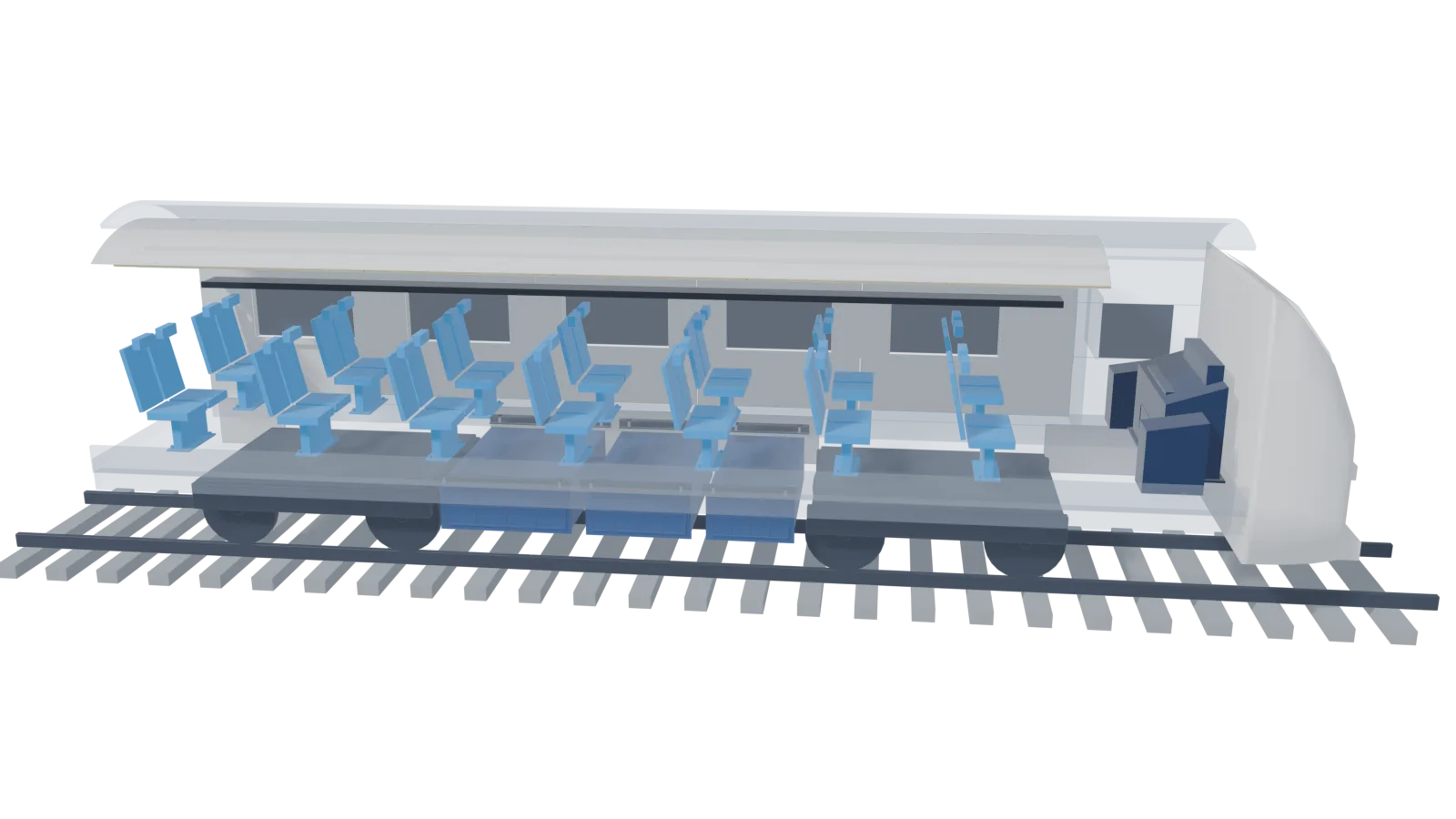
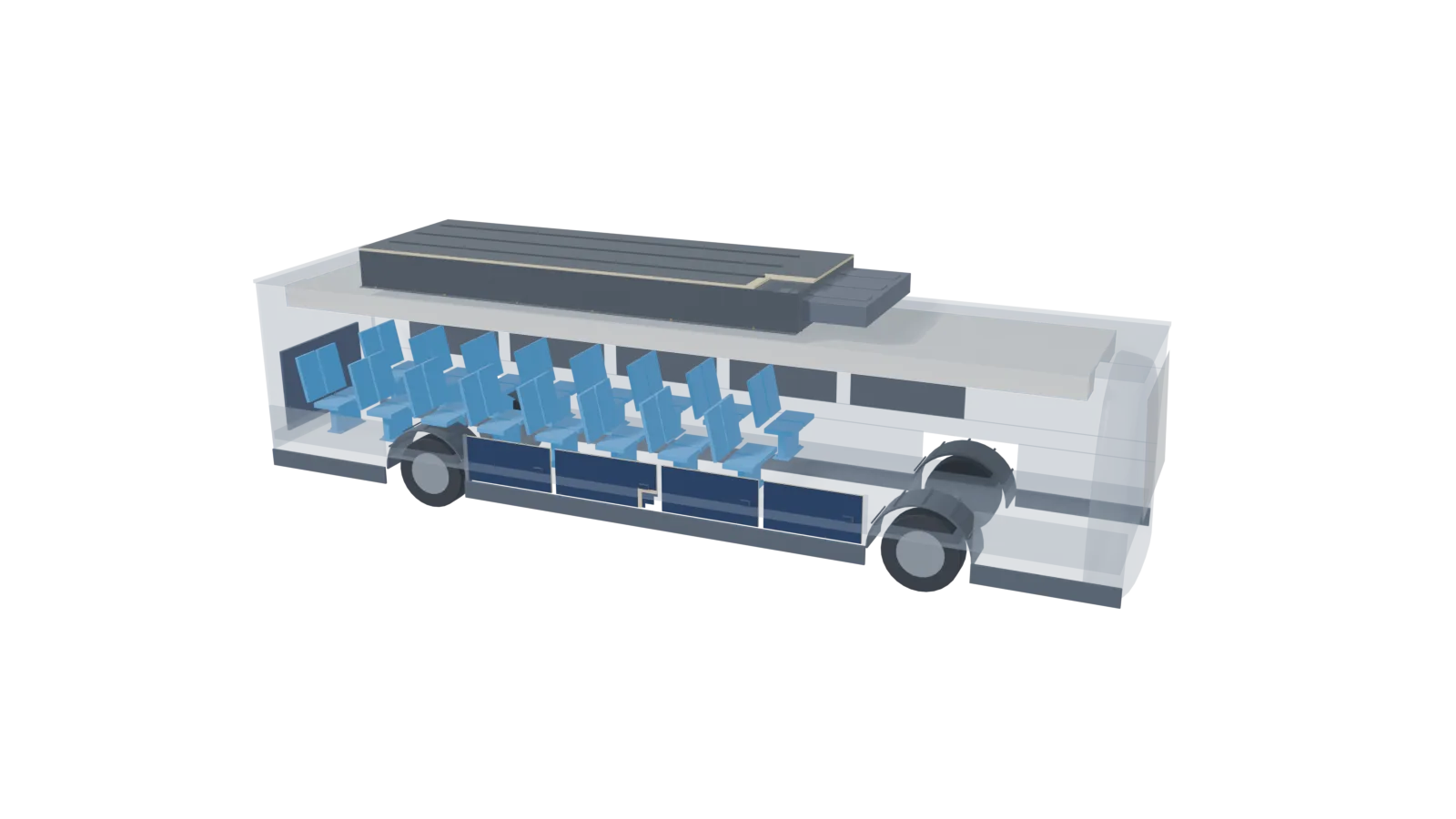
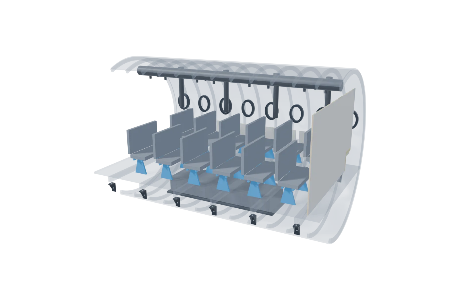
Generic passenger coach in cutaway, with the carbody in translucent grey. Click a part to zoom in and see its engineering sheet: process, fixing, lightweighting, advantages and series.

Render of a generic passenger coach in cutaway, with linings, ceiling, seats, driver desk, brackets, enclosures and front end

Drag to rotate · scroll or pinch to zoom · click a part to zoom in

01

Interior side panels

Location
Saloon walls, with 3D window frame.
Recommended material
Rail SMC HL3 · Structural Phenolic SMC 55% GF
Requirement / key data
EN 45545-2 · R1 up to HL3 (Rail SMC HL3). Alternative Structural Phenolic SMC: HL3, requirement depending on application.
1Part detail and process
Panel with 3D window frame, reveal and sill in a single pressing, rib grid on the back face and bosses with hidden inserts. Typical thickness of 2.5 to 6 mm for moulded parts. 5-axis waterjet trimming (0°–64°) and in-house CNC machining. Finish: technical visible face in the material colour.
2Assembly and fixing to the structure
  • M5–M12 threaded metal inserts, moulded in or installed cold or hot into reinforced bosses.
  • Perimeter overlap flanges to fit the adjacent parts.
3Lightweighting: ribbed monolithic or sandwich
Proposed solution: ribbed monolithic. Thin wall with 3D ribs, bosses and inserts where the loads arrive — right for compact parts or point loads. For large spans, a sandwich panel is assessed.
4Advantages over the traditional alternative
Compared with flat panels assembled with profiles — Rail SMC HL3: classified EN 45545-2 R1, R2, R3, R6, R7 and R17 up to HL3 by an ENAC-accredited laboratory; fewer parts and joints than an assembled solution.
5Series and manufacturing capacity
Typical series (indicative): 50 to 500 pcs/year, typical of rail, aerospace or space programmes. Press: P30 or P7 (6,000 kN, 1,850 × 1,400 and 1,600 × 1,400 mm platens). In-house fleet of 7 presses from 150 to 1,250 t, with a largest platen of 3,500 × 1,800 mm. The steel mould is amortised over the series: the higher the volume, the lower the tooling cost per part; for short runs we compare with other solutions.
Request a study of this part →
02

Curved modular ceiling with HVAC

Location
Saloon ceiling with air channels and diffusers.
Recommended material
Rail SMC HL3 · Structural Phenolic SMC 55% GF
Requirement / key data
EN 45545-2 · R1 up to HL3 (Rail SMC HL3). Alternative Structural Phenolic SMC: HL3, requirement depending on application.
1Part detail and process
Large curved sandwich module (layers visible at the cut), with integrated HVAC channel and louvred diffusers. Typical thickness of 2.5 to 6 mm for moulded parts. 5-axis waterjet trimming (0°–64°) and in-house CNC machining. Finish: technical visible face in the material colour.
2Assembly and fixing to the structure
  • M5–M12 threaded metal inserts, moulded in or installed cold or hot into reinforced bosses.
  • Perimeter overlap flanges to fit the adjacent parts.
3Lightweighting: ribbed monolithic or sandwich
Proposed solution: sandwich panel. Moulded skins with a lightweight self-extinguishing core, selected for the fire requirement, multiply flexural stiffness over large spans compared with a monolithic panel of the same weight; the actual weight saving is quantified in each part study. Compact parts are solved as ribbed monolithic.
4Advantages over the traditional alternative
Compared with flat panels assembled with profiles — Rail SMC HL3: classified EN 45545-2 R1, R2, R3, R6, R7 and R17 up to HL3 by an ENAC-accredited laboratory; fewer parts and joints than an assembled solution.
5Series and manufacturing capacity
Typical series (indicative): 50 to 500 pcs/year, typical of rail, aerospace or space programmes. Press: P10 (1,250 t, 3,500 × 1,800 mm platen) or P8 (10,000 kN, 2,800 × 1,800 mm). In-house fleet of 7 presses from 150 to 1,250 t, with a largest platen of 3,500 × 1,800 mm. The steel mould is amortised over the series: the higher the volume, the lower the tooling cost per part; for short runs we compare with other solutions.
Request a study of this part →
03

Load-bearing seat shells

Location
Backrest, seat and pedestal of each seat.
Recommended material
Rail SMC HL3
Requirement / key data
EN 45545-2 · R6 up to HL3 (Rail SMC HL3).
1Part detail and process
Vandal-resistant shell with rear rib grid, headrest and bosses with metal inserts for fixing to the pedestal. Typical thickness of 2.5 to 6 mm for moulded parts. 5-axis waterjet trimming (0°–64°) and in-house CNC machining. Finish: technical visible face in the material colour.
2Assembly and fixing to the structure
  • M5–M12 threaded metal inserts, moulded in or installed cold or hot into reinforced bosses.
  • Metal torque-limiting bushings in through holes, so tightening does not cause composite creep under vibration.
3Lightweighting: ribbed monolithic or sandwich
Proposed solution: ribbed monolithic. Thin wall with 3D ribs, bosses and inserts where the loads arrive — right for compact parts or point loads. For large spans, a sandwich panel is assessed.
4Advantages over the traditional alternative
Compared with cut, welded and painted steel sheet — Rail SMC HL3: classified EN 45545-2 R1, R2, R3, R6, R7 and R17 up to HL3 by an ENAC-accredited laboratory; fewer parts and joints than an assembled solution.
5Series and manufacturing capacity
Typical series (indicative): 50 to 500 pcs/year, typical of rail, aerospace or space programmes. Press: P22 or P20 (4,000 and 2,500 kN, 1,000 × 1,000 and 800 × 800 mm platens). In-house fleet of 7 presses from 150 to 1,250 t, with a largest platen of 3,500 × 1,800 mm. The steel mould is amortised over the series: the higher the volume, the lower the tooling cost per part; for short runs we compare with other solutions.
Request a study of this part →
04

Driver’s desk

Location
Driving console with side modules.
Recommended material
SMC + PIMC in-mould painting, Class A
Requirement / key data
EN 45545-2 depending on its position in the cab: defined for each project.
1Part detail and process
One-piece ergonomic desk with control recess, instrument hood, ventilation grille and fixing flange with inserts. Typical thickness of 2.5 to 6 mm for moulded parts. 5-axis waterjet trimming (0°–64°) and in-house CNC machining. Finish: PIMC in-mould painting, Class A.
2Assembly and fixing to the structure
  • M5–M12 threaded metal inserts, moulded in or installed cold or hot into reinforced bosses.
  • Perimeter overlap flanges to fit the adjacent parts.
3Lightweighting: ribbed monolithic or sandwich
Proposed solution: ribbed monolithic. Thin wall with 3D ribs, bosses and inserts where the loads arrive — right for compact parts or point loads. For large spans, a sandwich panel is assessed.
4Advantages over the traditional alternative
Compared with cut, welded and painted steel sheet — SMC with PIMC in-mould painting: Class A finish straight from the press, with no paint booth afterwards and no corrosion.
5Series and manufacturing capacity
Typical series (indicative): 50 to 500 pcs/year, typical of rail, aerospace or space programmes. Press: P30 or P7 (6,000 kN, 1,850 × 1,400 and 1,600 × 1,400 mm platens). In-house fleet of 7 presses from 150 to 1,250 t, with a largest platen of 3,500 × 1,800 mm. The steel mould is amortised over the series: the higher the volume, the lower the tooling cost per part; for short runs we compare with other solutions.
Request a study of this part →
05

Equipment beams and brackets

Location
Underfloor frames and luggage rack brackets.
Recommended material
CSMC Carbon 57%
Requirement / key data
Secondary structure. The CSMC datasheet includes no EN 45545-2 classification: in areas with a fire requirement it is validated in the study.
1Part detail and process
I-beams and brackets with web and flanges moulded in one go, with compression bushings and galvanic insulation washers at each support. Typical thickness of 2.5 to 6 mm for moulded parts. 5-axis waterjet trimming (0°–64°) and in-house CNC machining. Finish: technical visible face with controlled roughness in bonding areas.
2Assembly and fixing to the structure
  • Metal torque-limiting bushings in through holes, so tightening does not cause composite creep under vibration.
  • Galvanic couple insulation (insulating washers and gaskets) where the carbon part is fixed onto aluminium.
  • M5–M12 threaded metal inserts, moulded in or installed cold or hot into reinforced bosses.
3Lightweighting: ribbed monolithic or sandwich
Proposed solution: ribbed monolithic. Thin wall with 3D ribs, bosses and inserts where the loads arrive — right for compact parts or point loads. For large spans, a sandwich panel is assessed.
4Advantages over the traditional alternative
Compared with machined or cast aluminium — CSMC Carbon 57%: 1.51 g/cm³ vs 2.70 for aluminium (−44% at equal volume), tensile 370 MPa, modulus 41.5 GPa and +113% specific strength (245 vs 115 MPa·cm³/g).
5Series and manufacturing capacity
Typical series (indicative): 50 to 500 pcs/year, typical of rail, aerospace or space programmes. Press: P22 or P20 (4,000 and 2,500 kN, 1,000 × 1,000 and 800 × 800 mm platens). In-house fleet of 7 presses from 150 to 1,250 t, with a largest platen of 3,500 × 1,800 mm. The steel mould is amortised over the series: the higher the volume, the lower the tooling cost per part; for short runs we compare with other solutions.
Request a study of this part →
06

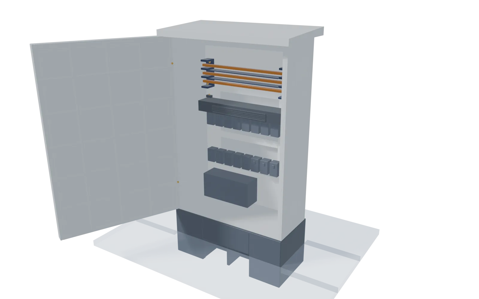
Underframe electrical enclosures

Location
Equipment enclosures and internal insulating plate.
Recommended material
Electrical SMC V-0 / CTI 600
Requirement / key data
UL 94 V-0 (3 mm) · glow wire 960 °C · CTI 600 · 16 kV/mm. EN 45545-2 depending on location: confirmed for each project.
1Part detail and process
Enclosure with ribbed lid, labyrinth sealing lip, ventilation grille and inserts at the lid corners. Typical thickness of 2.5 to 6 mm for moulded parts. 5-axis waterjet trimming (0°–64°) and in-house CNC machining. Finish: technical visible face in the material colour.
2Assembly and fixing to the structure
  • M5–M12 threaded metal inserts, moulded in or installed cold or hot into reinforced bosses.
  • Perimeter lip or channel for a sealing elastomer gasket.
  • Hinge and lock seats moulded with their inserts, with no welded reinforcements.
3Lightweighting: ribbed monolithic or sandwich
Proposed solution: ribbed monolithic. Thin wall with 3D ribs, bosses and inserts where the loads arrive — right for compact parts or point loads. For large spans, a sandwich panel is assessed.
4Advantages over the traditional alternative
Compared with cut, welded and painted steel sheet — Electrical SMC V-0 / CTI 600: 16 kV/mm, CTI 600, glow wire 960 °C, HDT > 250 °C, dielectric constant 4 and UL 94 V-0 at 3 mm. Corrosion-free, weld-free and inherently insulating.
5Series and manufacturing capacity
Typical series (indicative): 50 to 500 pcs/year, typical of rail, aerospace or space programmes. Press: P30 or P7 (6,000 kN, 1,850 × 1,400 and 1,600 × 1,400 mm platens). In-house fleet of 7 presses from 150 to 1,250 t, with a largest platen of 3,500 × 1,800 mm. The steel mould is amortised over the series: the higher the volume, the lower the tooling cost per part; for short runs we compare with other solutions.
Request a study of this part →
07

Aerodynamic front end and skirts

Location
Front fairing and large-format skirts.
Recommended material
Structural Phenolic SMC 55% GF
Requirement / key data
Structural Phenolic SMC: UL 94 V-0 @ 1.2 mm and LOI > 100%. Where the specification requires R7 (exterior), Rail SMC HL3 covers it.
1Part detail and process
Large front end with louvred air intake and headlight seats, and skirts with rear ribs and inserts; moulded on the 1,250 t press. Typical thickness of 2.5 to 6 mm for moulded parts. 5-axis waterjet trimming (0°–64°) and in-house CNC machining. Finish: technical visible face in the material colour.
2Assembly and fixing to the structure
  • M5–M12 threaded metal inserts, moulded in or installed cold or hot into reinforced bosses.
  • Perimeter overlap flanges to fit the adjacent parts.
  • Metal torque-limiting bushings in through holes, so tightening does not cause composite creep under vibration.
3Lightweighting: ribbed monolithic or sandwich
Proposed solution: ribbed monolithic. Thin wall with 3D ribs, bosses and inserts where the loads arrive — right for compact parts or point loads. For large spans, a sandwich panel is assessed.
4Advantages over the traditional alternative
Compared with flat panels assembled with profiles — Structural Phenolic SMC 55% GF: 1.84 g/cm³, flexural 350 MPa, Charpy 120 kJ/m², UL 94 V-0 at 1.2 mm, LOI > 100% and 0.00% moulding shrinkage (indicative datasheet values). A single 3D part with no bolted joints.
5Series and manufacturing capacity
Typical series (indicative): 50 to 500 pcs/year, typical of rail, aerospace or space programmes. Press: P10 (1,250 t, 3,500 × 1,800 mm platen) or P8 (10,000 kN, 2,800 × 1,800 mm). In-house fleet of 7 presses from 150 to 1,250 t, with a largest platen of 3,500 × 1,800 mm. The steel mould is amortised over the series: the higher the volume, the lower the tooling cost per part; for short runs we compare with other solutions.
Request a study of this part →

Generic, illustrative model: it does not represent any real vehicle. Indicative recommendations: the final choice depends on the R requirement, HL level and thickness of each project. EN 45545-2 classifications apply to the tested material and are not a type approval of the part.